
The allure of a rear discharge toilet, particularly in challenging plumbing situations or when aiming for a sleek, modern aesthetic, is undeniable. Unlike traditional toilets that rely on gravity and a standard floor drain, rear discharge models expel waste through a port at the back, connecting to a macerator pump that grinds waste into a fine slurry before it’s propelled through smaller diameter pipes.
This innovation opens up possibilities for bathroom installations in basements, garages, or even above existing plumbing lines where conventional drainage is impractical or prohibitively expensive. However, the “rough plumbing” phase, the initial installation of pipes, vents, and connections, for these specialized units requires a meticulous approach, distinct from standard toilet setups.
Understanding the nuances of this process is crucial for a successful, code-compliant, and long-lasting bathroom addition.
This guide will explore the intricacies of rough plumbing for rear discharge toilets, covering everything from system design and pipe selection to ventilation requirements and pump integration. We’ll delve into the specific considerations that set these systems apart, offering practical advice and insights for homeowners, DIY enthusiasts, and even seasoned plumbers encountering this technology for the first time.
By mastering the fundamentals of rear discharge rough plumbing, you can confidently embark on projects that transform unconventional spaces into functional and comfortable bathrooms.
Key Takeaways
- Macerator Pump is Central: The core of a rear discharge toilet system is the macerator pump, which grinds waste and propels it through small pipes. Rough plumbing must accommodate this unit.
- Pipe Size and Material: Unlike standard toilets using 3-inch or 4-inch drain lines, rear discharge systems can use 1-inch to 2-inch pipes, requiring specific materials like PVC or ABS.
- Discharge Line Routing: The discharge line can run horizontally or vertically for significant distances, but slope and friction loss must be carefully calculated.
- Ventilation is Critical: Proper venting is essential for system function and preventing sewer gas odors, often requiring specialized vent configurations.
- Electrical Requirements: The macerator pump needs a dedicated electrical circuit, necessitating planning for power supply during rough-in.
- Code Compliance: Local plumbing codes dictate specific requirements for materials, venting, and installation, which must be adhered to.
- Professional Consultation: For complex installations or uncertainty, consulting a licensed plumber is highly recommended.

Credit: www.youtube.com
Understanding The Rear Discharge Toilet System
Before diving into the rough plumbing, it’s vital to grasp how a rear discharge toilet operates. The primary differentiator is the absence of a large, gravity-fed waste line directly behind the toilet. Instead, waste enters a macerator unit, which is typically integrated into the toilet itself or sits directly behind it.
This unit contains a cutting mechanism that pulverizes solid waste and toilet paper into a liquid slurry. Once macerated, a powerful pump expels this slurry through a much smaller diameter discharge pipe. This pipe can then be routed horizontally for considerable distances, or even vertically, to connect to the main sewer line or a septic system.
The advantages are significant: it bypasses the need for a traditional, large-diameter drain pipe directly below the fixture. This makes it ideal for retrofitting bathrooms in locations where breaking up concrete floors for standard plumbing is impractical or cost-prohibitive, such as basements or older homes. It also allows for more flexible bathroom design, as the toilet doesn’t need to be positioned directly above a main stack. However, this flexibility comes with its own set of requirements for the rough plumbing. The system is entirely dependent on the macerator pump’s functionality, and the discharge piping must be designed to handle the pumped effluent efficiently.
Designing Your Rough Plumbing Layout
The design phase for rough plumbing a rear discharge toilet is fundamentally different from a standard toilet installation. The focus shifts from gravity flow through large pipes to pressurized flow through smaller pipes, driven by a pump. This requires careful consideration of pipe routing, slope, and the integration of the macerator unit.
Determining Discharge Line Routing
The primary challenge is planning the path of the discharge line. Unlike a standard toilet, which needs a direct, downward path to a floor drain, a rear discharge toilet’s effluent is pumped. This means the discharge pipe can:
- Run Horizontally: It can be routed horizontally along walls or under floors for substantial distances. However, it’s crucial to maintain a slight downward slope away from the macerator pump, typically between 1/8 inch and 1/4 inch per linear foot, to aid gravity in assisting the pumped flow and prevent solids from settling.
- Run Vertically: It can also ascend vertically to reach an existing drain line located above the toilet. Most macerator pumps can push waste upwards for a considerable height, often up to 15-20 feet, but always check the manufacturer’s specifications for your specific unit. The pipe must be securely fastened, and any vertical rise should ideally be as short as possible.
- Connect to Existing Plumbing: The ultimate goal is to connect this discharge line to your home’s main drain-waste-vent (DWV) system. This typically involves tapping into an existing vertical waste stack or a horizontal drain line of adequate size.
Incorporating The Macerator Pump
The macerator pump is the heart of the system. Rough plumbing must account for its physical presence and its connection to both the toilet and the discharge piping.
- Location: The pump unit will be situated behind or integrated with the toilet. Ensure there is adequate space for maintenance and potential servicing. Some units require specific clearances from walls.
- Toilet Connection: The toilet’s waste outlet connects directly to the pump’s inlet. This connection is usually made with a flexible rubber coupling, which helps absorb vibration.
- Discharge Outlet: The pump has a discharge port that connects to the small diameter pipe. This connection is critical and must be watertight. A union fitting is often recommended here to allow for easier disconnection if the pump needs to be removed.
Pipe Material And Size Selection
This is a significant departure from standard plumbing. For rear discharge toilets, the discharge line is typically much smaller and requires specific materials:
- Pipe Diameter: Most macerator pumps are designed to discharge into pipes ranging from 1 inch to 2 inches in diameter. The exact size depends on the pump’s capacity and the required length and height of the discharge run. Always consult the manufacturer’s manual for recommended pipe sizes for your specific model and installation scenario.
- Material: PVC (Polyvinyl Chloride) or ABS (Acrylonitrile Butadiene Styrene) are the most common and recommended materials for the discharge line. These plastic pipes are corrosion-resistant, lightweight, and easy to join using solvent cement. Metal pipes are generally not recommended due to potential corrosion and the risk of solids adhering to rough surfaces.
Example Scenario: Basement Bathroom
Consider a homeowner wanting to add a bathroom in a basement where the main sewer line is located on the first floor.
- Toilet Placement: The toilet is installed against a basement wall.
- Macerator Unit: The macerator pump is installed directly behind the toilet.
- Discharge Pipe: A 1.5-inch PVC pipe is connected to the pump’s discharge.
- Routing: This pipe is routed horizontally along the basement wall, maintaining a slight downward slope towards the existing plumbing stack.
- Connection: The 1.5-inch pipe is then routed upwards to connect to a 3-inch or 4-inch vertical waste stack on the first floor. This connection point must be above the flood rim of any fixture on that stack to prevent backflow.
- Ventilation: A new vent line is run from the discharge pipe (near the connection point to the main stack) up through the roof, ensuring proper air circulation.
This setup allows for a fully functional bathroom without the extensive and costly work of breaking concrete to install a traditional gravity drain.
Credit: terrylove.com
Venting Requirements For Rear Discharge Systems
Proper venting is as critical for a rear discharge toilet system as it is for a standard one, perhaps even more so due to the pressurized nature of the discharge. Without adequate ventilation, the system can experience siphoning, where the flow of waste pulls air from the vent, potentially creating a vacuum that disrupts flushing and allows sewer gases to enter the bathroom.
Understanding The Purpose Of Venting
Vents serve two primary functions:
- Preventing Siphonage: They allow air to enter the drainage system, breaking any vacuum created by flowing waste, thus maintaining proper water seals in traps.
- Allowing Sewer Gases to Escape: They provide a path for unpleasant and potentially harmful sewer gases to vent safely outside, usually through the roof.
Venting Configurations For Rear Discharge Toilets
The specific venting configuration depends heavily on how the discharge line connects to the main DWV system and local plumbing codes.
- Connection to Existing Vent Stack: If the discharge line connects to an existing vertical waste stack that is properly vented, you may simply need to tie your new vent line into that stack. The connection point must be above the flood level rim of the highest fixture served by that stack.
- New Vent Stack: In some cases, especially with long horizontal runs or significant vertical lifts, a dedicated vent stack might be necessary. This vent would run independently up through the roof.
- Air Admittance Valves (AAVs): In certain jurisdictions and situations, an Air Admittance Valve (AAV) can be used instead of a traditional vent pipe extending through the roof. An AAV is a one-way valve that opens to admit air into the system when negative pressure occurs but seals to prevent sewer gases from escaping.
- Pro Tip: Always check local building codes to confirm if AAVs are permitted for this application and to understand their specific installation requirements (e.g., height above flood level, accessibility for maintenance).
Vent Pipe Sizing And Slope
- Sizing: The vent pipe size is determined by the number of fixture units it serves and the length of the vent run. For a single rear discharge toilet, a 2-inch vent pipe is often sufficient, but this should be confirmed based on the system’s overall load and local codes.
- Slope: Like drain pipes, vent pipes must also be installed with a slight upward slope away from the fixture towards the point where they connect to the main vent system or exit the building. This prevents condensation from pooling in the vent pipe.
Example: Venting A Basement Bathroom Extension
Imagine the basement bathroom’s discharge line connects to a first-floor waste stack.
- Connection Point: The 1.5-inch PVC discharge line connects to the existing 3-inch waste stack approximately 6 feet above the basement floor.
- New Vent Line: A new 2-inch PVC vent pipe is connected to the 3-inch waste stack just above the point where the discharge line enters. This connection is made with a wye fitting to ensure a smooth flow of air.
- Routing: The 2-inch vent pipe runs vertically upwards, parallel to the waste stack, through the first floor, second floor, and finally through the roof.
- Termination: The vent pipe terminates above the roofline at a code-compliant height, typically 6-12 inches, with a vent cap to prevent rain and debris from entering.
This setup ensures that air can enter the discharge line when the pump operates, preventing siphoning and allowing waste to flow freely towards the main sewer.
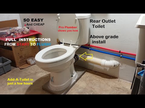
Credit: www.youtube.com
Electrical Requirements And Considerations
A rear discharge toilet system is fundamentally an electric appliance. The macerator pump requires power to operate, and this necessitates careful planning during the rough-in phase to ensure a safe, code-compliant, and accessible electrical connection.
Dedicated Circuit
- Requirement: The macerator pump must be connected to a dedicated electrical circuit. This means the circuit breaker controlling the pump should not power any other outlets or fixtures in the house. This prevents overloading the circuit and ensures the pump has consistent power when needed.
- Amperage: Check the pump manufacturer’s specifications for the required amperage and voltage. This will determine the appropriate size of the circuit breaker (e.g., 15A or 20A) and the gauge of the electrical wire needed.
Wiring Installation
- During Rough-In: The electrical wiring for the pump should be run during the rough-in stage, alongside the plumbing. A conduit or Romex cable (e.g., 12/2 or 14/2 NM-B wire, depending on amperage) is typically used to run power from the electrical panel to the vicinity of the pump.
- Waterproofing: Since the pump is located in a bathroom environment, all electrical connections must be made within waterproof junction boxes and utilize GFCI (Ground Fault Circuit Interrupter) protected outlets. This is a critical safety measure to prevent electrical shock in a wet environment.
- Accessibility: The outlet for the pump should be positioned in a location that is accessible for plugging in the pump but also protected from direct water splashes. Often, this is behind the toilet tank or within a nearby cabinet.
Gfci Protection
- Mandatory: GFCI protection is mandatory for all bathroom receptacles and any outlet serving appliances in wet locations. A GFCI outlet or circuit breaker monitors the flow of electricity and will trip, cutting off power, if it detects an imbalance that could indicate a shock hazard.
- Testing: Regularly test the GFCI outlet (monthly is recommended) to ensure it is functioning correctly.
Example: Wiring For A New Basement Bathroom
If you’re adding a new basement bathroom:
- Panel Check: Determine if your main electrical panel has available breaker slots and sufficient capacity.
- Circuit Run: Run a new circuit from the panel using the appropriate gauge wire, protected by a GFCI breaker rated for the pump’s requirements (e.g., 20A).
- Route Wire: Route the wire through wall cavities or conduit to the location of the macerator pump.
- Junction Box: Install a waterproof junction box near the pump’s location.
- GFCI Outlet: Install a GFCI-protected receptacle inside the waterproof junction box.
- Connection: The pump’s power cord will plug into this GFCI outlet. Ensure the connection is secure and protected from moisture.
Warning: Electrical work can be dangerous. If you are not experienced with electrical wiring, it is highly recommended to hire a licensed electrician to perform this part of the installation. Improper wiring can lead to fire hazards, equipment damage, and serious injury.
Integrating With Main Drainage Systems
The final step in the rough plumbing process is connecting the rear discharge toilet’s system to the home’s main drain-waste-vent (DWV) system. This connection point is crucial for the overall functionality and code compliance of your plumbing.
Choosing The Connection Point
The location where the small-diameter discharge pipe joins the larger main drain line is critical.
- Vertical Stacks: Connecting to a vertical waste stack is often preferred. The connection should be made using a sanitary tee or wye fitting on the stack.
- Horizontal Drains: If connecting to a horizontal drain line, use a long-sweep sanitary tee or wye fitting to ensure smooth flow and minimize the risk of blockage.
- Height Considerations: The connection point must be above the flood level rim of any fixture served by that drain line downstream from the connection. This prevents sewage from backing up into the new bathroom. For example, if connecting to a stack that serves a sink on the first floor, your connection point must be higher than the sink’s overflow rim.
Pipe Transition And Fittings
- Reducing Fittings: You will need appropriate reducing fittings to transition from the small-diameter discharge pipe (e.g., 1.5-inch PVC) to the larger diameter of the main drain line (e.g., 3-inch or 4-inch ABS or cast iron).
- Weld/Connection Type: The method of connecting to the existing DWV system depends on the material of the existing pipes.
- PVC/ABS: Use primer and solvent cement for plastic-to-plastic connections.
- Cast Iron: Mechanical couplings (like Fernco or Mission couplings) are typically used to connect plastic pipes to cast iron pipes. Ensure the coupling is rated for DWV use and is properly secured.
Backwater Valves And Check Valves
- Check Valve: Most macerator pumps have an integrated check valve to prevent backflow into the pump. However, in some situations, particularly if the main drain line is prone to backups, installing an additional check valve on the discharge line *before* it connects to the main DWV system can provide extra protection.
- Backwater Valve: For added security, especially in basements or areas susceptible to sewer backups, consider installing a backwater valve on the main drain line *after* your connection point, or on a separate branch serving the new bathroom. This valve allows flow in one direction (towards the sewer) but automatically closes to prevent sewage from flowing back into the house.
Maintaining Slope
Even after connecting to the main DWV system, ensure that the final section of the discharge pipe leading to the connection point maintains its slight downward slope. This helps prevent any residual solids from settling out before they enter the main system.
Example: Connecting To A First-floor Waste Stack
Continuing the basement bathroom example:
- Access: Access is gained to the existing 3-inch ABS waste stack on the first floor.
- Cutting: A section of the vertical stack is carefully cut out to accommodate a 3-inch ABS sanitary tee.
- Installing Tee: The sanitary tee is installed, with the branch of the tee oriented horizontally.
- Connecting Discharge Line: The 1.5-inch PVC discharge pipe from the basement is routed upwards and connected to the 3-inch branch of the sanitary tee using an appropriate reducing fitting and ABS primer/cement. Ensure the connection is made with a slight downward slope *into* the tee.
- Vent Connection: The new 2-inch vent pipe is connected to the top of the vertical portion of the sanitary tee using a wye fitting, ensuring proper slope upwards.
- Securing: All connections are verified, and the stack is properly supported.
This methodical approach ensures that the new rear discharge toilet system integrates seamlessly and safely with the existing plumbing infrastructure.
Common Rough Plumbing Challenges And Solutions
While rear discharge toilets offer significant advantages, their rough plumbing can present unique challenges. Understanding these potential pitfalls and their solutions can save time, money, and frustration.
Challenge: Insufficient Slope Or Long Horizontal Runs
- Problem: The discharge pipe needs to run horizontally for a significant distance to reach the main drain. If the slope is too shallow (less than 1/8 inch per foot), solids can settle, leading to clogs. If the run is excessively long, friction loss can reduce pump efficiency.
- Solution:
- Maximize Slope: Use the maximum allowable slope (up to 1/4 inch per foot) without creating issues with floor height or fixture placement.
- Shorten Run: If possible, re-route the pipe to minimize the horizontal distance.
- Pump Capacity: Ensure your macerator pump is rated for the total head (vertical lift) and equivalent length of the discharge pipe. Consult the manufacturer’s performance curve chart.
- Access Points: Install cleanout fittings at strategic points along long horizontal runs to allow for easier snaking and clearing of potential blockages.
Challenge: Incorrect Venting
- Problem: Inadequate venting leads to siphoning of fixture traps, gurgling sounds, and potential sewer gas odors. This can occur if the vent is too small, improperly sloped, too far from the fixture, or blocked.
- Solution:
- Code Review: Strictly adhere to local plumbing codes regarding vent sizing, termination, and distance from the trap arm.
- Proper Slope: Ensure all vent pipes slope upwards continuously.
- AAVs: Consider an Air Admittance Valve (AAV) if permitted by code and appropriate for the situation, but understand its limitations and maintenance requirements.
- Professional Assessment: If problems persist, a plumber can diagnose venting issues, which might involve installing additional vents or re-routing existing ones.
Challenge: Electrical Connection Issues
- Problem: The pump doesn’t run, trips the breaker, or the GFCI outlet keeps tripping. This could be due to incorrect wiring, a faulty pump, undersized wiring, or moisture issues.
- Solution:
- Verify Wiring: Double-check all electrical connections against the pump manufacturer’s diagram and local electrical codes. Ensure correct wire gauge and breaker size.
- GFCI Test: Test the GFCI outlet itself. If it trips immediately upon plugging in the pump, suspect a short circuit in the pump or its cord.
- Moisture: Ensure all connections are dry and protected within waterproof enclosures. Moisture ingress is a common cause of GFCI tripping.
- Professional Electrician: For persistent electrical issues, call a licensed electrician.
Challenge: Connecting To Older Plumbing Materials (e.g., Cast Iron)
- Problem: Transitioning from modern PVC/ABS discharge pipes to older, potentially brittle cast iron pipes requires specific techniques to avoid damage.
- Solution:
- Mechanical Couplings: Use approved rubber sleeve couplings with stainless steel clamps (e.g., Mission or Fernco couplings) designed for transitioning between dissimilar pipe materials.
- Clean Pipe Ends: Ensure both the cast iron and plastic pipe ends are clean, smooth, and square before installing the coupling.
*